DMF Relay Executive Summary
The DMF equipment has two basic component capabilities, 1) a fast and secure SSR generator protection relay, and 2) a high speed Digital Fault Recorder.
The DMF protection has two trip function, 1) steady state SSR detection and trip, and 2) fast transient resonant protection. The protection function measures the torsional velocity of the generator, and the generator voltages and currents.
The steady state protection uses digital methods to isolate the torsional responses of the turbine-generator. This protection detects unstable velocity response and has trip times coordinated with turbine-generator shaft fatigue capability, in the form of a time over-torque relay characteristic.
The fast transient protection is a new invention to provide very fast trip featuring both secure and dependable operation. This protection uses both velocity and acceleration measurements and uses the turbine-generator itself as the means to detect response without delay. Each mode is armed to trip based on exceeding a certain level of velocity. Trip is delivered based on a time over-acceleration function. Trip output from the DMF relay is typically available within one cycle of torsional frequency for worst cases. Lower responding acceleration events trip in correspondingly longer times. The trip is issued well before the peak transient response has been achieved, therefore limiting damage to the turbine-generator.
The Oscillograph DFR function is provided to allow quick evaluation of the SSR events for SSR severity and trip-point relative to local time and relative to event inception. The DFR provides event triggering based on relay targets, and based on conventional triggers for over and under voltage and current, and rate-of-change of response.
The DFR and DMF human interface is provided through a Windows 2000® computer equipped for Ethernet communication for enterprise-wide data access.
Cubicle Format DMF Module Front Panel
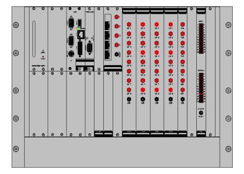
Cubicle Format DMF Module - Inside Front Panel View

Cubicle Format DMF Module - Rear Panel
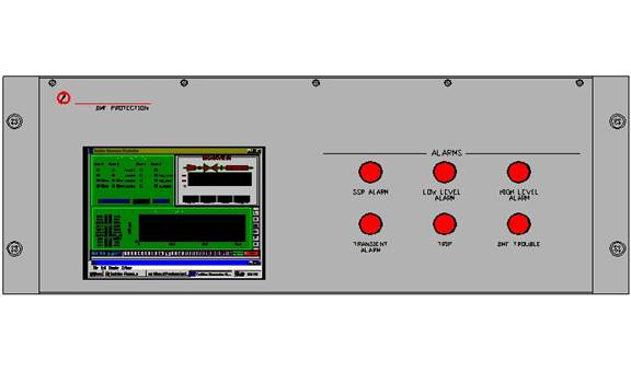
Low Profile Panel Format, DMF Front Panel View
- New Configuration Available 3Q 2004

Low Profile Panel Format, DMF Rear Panel View - New Configuration Available 3Q 2004
Maximum Capacity Configuration Shown
Detailed Specification
Analog Input Signals - up to 32 channels
Type - Differential
Isolation - 5000 volts
Bandwidth - 100 KHz
PT Secondary Voltage - 240v, short term 2 times rated max
CT Secondary Current - 5 amp, short term 20 times rated max
Other Analog Signals - 10v nominal
Digital Inputs - up to 32 channels
Type – Single Ended
Isolation – 250 volts
Digital Outputs – up to 8 relay outputs
Type ‘C’ Form (NO/NC)
Analog to Digital Conversion
Bit resolution – 18 bits (14 bit converter, 4 bit AGC)
Sample Rate – 7200 Hz (120/144 samples per cycle at 60/50 Hz)
Anti-Aliasing Filter – 8 Pole, Linear Phase, Sample rate adjustable
Time Input Options
NTP – TCP/IP three sources
IRIG-A/B
Satellite GPS Receiver
Host Computer
Operating Environment -Win2K
Processor - Pentium III 850 MHz
Memory - 256 M byte RAM
Storage - 16 G byte hard disk
Communications -10/100 Mb/s Ethernet
Enclosure - 4U 19” Rack Mounting
Local Human Interface – 6” diagonal LCD 800 by 600
Input Power
AC 120/240 V AC 50/60 Hz
DC 125V – 150 Watt
Environment
Operating
Non-Condensing Atmosphere
Applicable Standards
IEEE Standard C37.90.1, “ SWC requirements for fast transient immunity.”
IEEE Standard C37.90-1989 Section 8, “Requirements for dielectric withstand.”
IRIG Standard 200-95, “IRIG Standard Time Formats.” Telecommunications Working Group, Inter-Range Instrumentation Group, Range Commanders Council.
IEEE Standard C37.111-1999, “IEEE Standard Common Format for Transient Data Exchange (COMTRADE) for Power Systems.
IEEE Standard 1344-1995, “IEEE Standard for Synchrophasors for Power Systems.”
IEEE Standard C57.13-1993, “Standard Requirement for Instrument Transformers.”